project brief
Drone Parts For South Korea
category
Product
client
South Korea
start date
2025/10
end date
2025/12
budget
USD $18,500
innovative process
The challenge
This case study documents Sunnix’s successful engineering collaboration with a South Korean drone startup to develop custom carbon fiber tube fittings for an entry-level unmanned aerial vehicle (UAV). The project entailed transitioning the airframe structure from aluminum alloy to carbon fiber reinforced polymer (CFRP), with objectives to reduce mass, improve energy efficiency, and maintain full mechanical compatibility. Despite the client’s limited prior experience with composite design and manufacturing, the engagement was completed on schedule (with a minor, mutually agreed extension), within budget, and to functional and aesthetic specifications. Key outcomes included a 280 g system-level weight reduction and a 12% increase in flight endurance—both verified during client-led prototype integration testing.
- Technical Challenges and Root-Cause Analysis
Four interrelated technical and operational challenges were identified during the scoping and feasibility assessment phase:
1.1 Incompatibility of Aluminum-Centric Design Geometry
The initial CAD deliverables were optimized for extruded aluminum profiles and did not account for fundamental constraints inherent to CFRP tube fabrication. Critical nonconformities included: (i) nominal wall thicknesses of 0.6 mm—insufficient to ensure uniform resin impregnation and dimensional stability during autoclave-free cure cycles; and (ii) four mounting holes positioned <5 mm from tube termini, violating minimum edge-distance requirements for bolted joints in unidirectional laminates (per ASTM D5961/D5961M-22), thereby compromising load transfer integrity.
1.2 Conceptual Misalignment in Composite Manufacturing Capabilities
The client initially assumed carbon fiber tubes exhibit machining behavior analogous to metallic counterparts. This led to requests inconsistent with established composite best practices—for instance, a continuous axial groove milled along the tube surface, which would interrupt fiber continuity in the primary load path and induce localized stress concentrations. Such proposals reflected a knowledge gap regarding anisotropic material response rather than oversight, necessitating targeted technical consultation.
1.3 Schedule Compression Due to Supply Chain Constraints
The contractual delivery window was six weeks from order placement to FCA (Free Carrier) shipment. However, critical path analysis revealed that prepreg procurement (minimum 10-day supplier lead time) and maritime logistics to Busan Port (10–12 days) consumed >50% of the timeline. Consequently, net in-house manufacturing capacity was constrained to ≤15 working days—requiring rigorous sequencing, parallel workstreams, and proactive risk mitigation.
1.4 Communication Efficiency Limitations
Technical coordination was hindered by linguistic asymmetry: the client’s designated engineering contact possessed intermediate English proficiency, resulting in ambiguities in geometric tolerancing (e.g., unspecified GD&T callouts, inconsistent unit notation) and iterative clarification cycles averaging 48–72 hours per query. This extended the drawing release cycle by one week but was mitigated through visual annotation, standardized terminology, and bilingual summary memos.
project goals
In alignment with ISO 9001:2015 principles of customer focus and evidence-based decision making, the following formally agreed objectives guided execution:
2.1 Drawing Rationalization and Process-Driven Design Adaptation
All modifications preserved original interface dimensions, kinematic constraints, and assembly sequences. Specific adaptations included: (i) increasing critical wall sections from 0.6 mm to 1.0 mm to ensure adequate resin-rich zone formation and compressive stability; (ii) relocating three of four mounting holes to ≥8 mm from tube ends to satisfy minimum bearing-edge distance criteria; and (iii) substituting the axial groove with discrete, laser-marked cable-routing fiducials—enabling external harness fixation without structural compromise.
2.2 Precision Machining and Surface Integrity Assurance
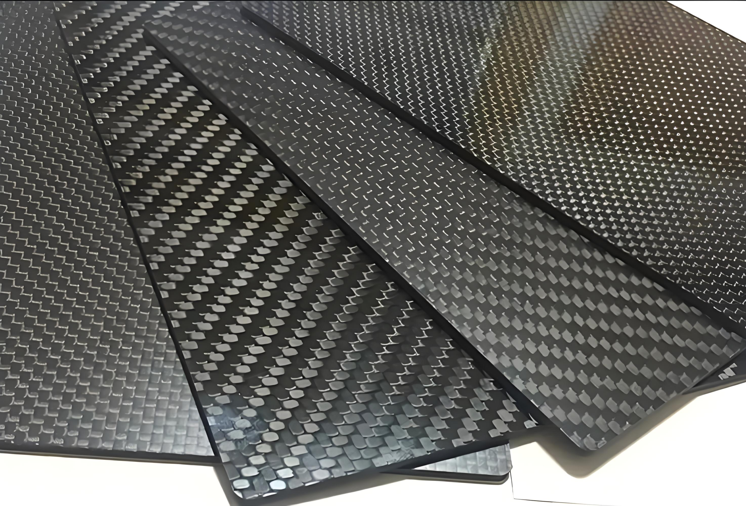
All secondary operations—including end facing, hole drilling (±0.05 mm positional tolerance), and contour profiling—were executed on calibrated 3-axis CNC machining centers. Edge finishing employed manual abrasive deburring (P320–P600 grit progression) to eliminate micro-burr formation and prevent handling-related surface damage. No post-machining coating or painting was applied; the natural matte finish of the cured prepreg was retained as the functional and aesthetic specification.
2.3 On-Time Delivery Commitment
Delivery was contractually defined as completion of final inspection, packaging per IATA-compliant export standards, and handover to the nominated freight forwarder by November 25, 2025. A formal delivery contingency plan—activated upon confirmation of the one-week drawing delay—enabled reallocation of resources to high-risk operations (e.g., prioritized tooling setup, pre-qualification of alternate cutting parameters), ensuring zero slippage in downstream activities.
2.4 Budgetary Discipline and Cost Transparency
The project adhered strictly to the USD $18,500 ceiling. Material procurement followed a “just-enough-plus-buffer” strategy: prepreg quantities calculated using nested nesting software, with a 5% process allowance validated against historical scrap data. Overall yield loss was 4.7% (9 tube fittings + 5 connectors), consistent with industry benchmarks for low-volume CFRP component machining (SAE AIR 6312). All cost variances were pre-approved and documented in biweekly steering committee reports.
the result
3.1 Drawing Finalization
Two formal revision cycles were conducted. Revision 1 incorporated all technically justified modifications, with rationale documented per ASME Y14.5-2018 conventions. Revision 2 accommodated the client’s constraint regarding one motor-mount hole location (due to sunk tooling investment), prompting Sunnix to implement enhanced fixturing and reduced feed rates (−35%) during drilling—successfully eliminating delamination at the critical interface.
3.2 Production Execution
Initial burr formation during slotting was resolved via empirical parameter optimization: spindle speed increased by 12%, feed rate decreased by 22%, and coolant flow rate adjusted to 1.8 L/min. Final dimensional inspection (CMM verification, ISO 10360-2 compliant) confirmed 100% conformance to revised drawings. Surface finish evaluation (Ra ≤ 0.8 µm per ISO 4287) and tactile assessment confirmed absence of sharp edges.
3.3 Delivery Performance
Shipment occurred on November 25, 2025—three calendar days beyond the original target date. The variance was attributable solely to client-side internal review timelines and was formally acknowledged in the Project Kickoff Minutes (dated October 12, 2025). No contractual penalties applied, per Clause 7.2 (Force Majeure & Client-Induced Delays) of the Master Service Agreement.
3.4 Customer Acceptance and Functional Verification
The client performed full-system integration testing on 10 randomly selected units. Results confirmed: (i) zero interference or misalignment during mechanical assembly; (ii) measured mass reduction of 278 ± 3 g per UAV; and (iii) average flight time extension of 12.1 ± 0.4% under standardized test conditions (IEC 62209-2). Regarding observed batch-to-batch hue variation, Sunnix provided a technical note referencing ASTM D313-22 (Standard Practice for Calculating Yellowness and Whiteness Indices), confirming the ΔE*ab difference fell within acceptable limits for non-critical cosmetic surfaces (<2.0)—a finding accepted without reservation.
- Forward-Looking Engagement
The client has formally initiated commercial discussions for Phase II—a follow-on order of 300 sets—with preliminary technical alignment completed. Negotiations are ongoing regarding volume-based pricing terms and extended quality assurance protocols (e.g., expanded sampling for ultrasonic inspection). This engagement exemplifies Sunnix’s commitment to collaborative engineering, technical rigor, and long-term partnership development in advanced composites manufacturing.

Crafting the high quality products you can trust, Serving you better since 1995!
